Ultrasonic welding is particularly suited for assembling medical devices because it uses the device material itself to create the joint, obviating the need for adhesives. A fast, clean, efficient and repeatable process, ultrasonic welding is ideal for joining just about any plastic parts for many applications. To obtain these advantages, however, engineers must select a weldable material, design the joint, develop the fixtures, optimize the welding process, and finally, control it.
Ultrasonic welding joins thermoplastic parts by using high-frequency vibration (typically 20 to 40 kilohertz) to melt material at the junction of the parts. First patented in the 1960s, ultrasonic welding has since been refined for use in many applications. Related processes include ultrasonic staking, swaging and spot welding.
Many thermoplastics, both amorphous (such as polystyrene) and semicrystalline (such as nylon), can be ultrasonically welded. Ideally, both parts in a weld are made from the same material. However, many combinations of unlike plastics can be ultrasonically welded if their melting temperatures are fairly close.
During ultrasonic welding, the two parts are fixtured so they are aligned and touching. At the start of the process, a horn, which transfers ultrasonic energy, moves down to apply pressure to the top part. The horn then vibrates at high frequency, and the friction of one part vibrating against the other produces heat. This softens and melts the plastic at the interface between the parts, creating a weld.
Joint Design
While the concept of ultrasonic welding is simple, the process of designing a robust joint and developing an effective weld process can be quite complex. Typically, it starts with a nominal joint design, a nest and horn design, and the energy coupler gain to obtain the nominal vibration amplitude at the welded surfaces. Then, the process iterates between adapting the geometry of the joint and optimizing the weld process parameters (energy coupler gain, energy and energy envelope, pressure, and duration).
To create a good weld, the parts must make initial contact over a relatively small area compared to the finished weld area. This allows initiation of melting soon after ultrasonic vibrations are applied.
There are two common approaches for creating the small initial contact area: an energy-director joint and a shear joint.
An energy director is a feature molded into the bottom of the top part. The energy director is triangular in section, with the point of the triangle providing the initial contact between the two parts. The energy director concentrates the vibrational energy in a small contact area.
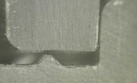
A shear joint provides strength and may be used to create a hermetic seal. The parts are designed to interfere initially in a small area. As ultrasonic vibrations are applied and the horn presses down on the parts, the top part melts its way into the bottom part. Many joint geometries are possible, but all use some way of providing a small initial contact area for the weld.
Beyond the Basics
Once you understand the fundamentals of joint design for ultrasonic welding, you can design joints that have features and functions other than just joining the two parts together.
For example, we recently designed an implantable, pressurized medical device that requires several ultrasonic welds for its manufacture. The final weld joins the cover of the device housing to the base. These two large circular parts, approximately 70 millimeters in diameter, telescope together as they are welded. In addition to providing structural integrity, the joint encompasses other functions and features.
For example, the joint includes features to control the weld and assembly geometry. Alignment is critical for a quality joint. Various features can be molded into the parts to align and locate them with respect to each other. The ultrasonic tool nest and horn can also be designed with features to ensure correct alignment during welding.
For example, a chamfer along the ID of the base part will push the upper piece inward as the weld progresses. Such a chamfer centers the two concentric enclosure pieces of our pressurized device. Alternatively, a slip fit could be designed between adjacent surfaces. This would prevent the top part from sliding away from the base part during welding.
To maintain a consistent height of the assembly, a stop can be molded into the base part. This is simply a shelf that prevents the top part from moving downward any further than necessary.
Engineers can also design joint features to contain flash and particles generated during welding. Flash or loose particles in a sensitive area could cause a medical device to fail.
In our pressurized device, the joint is designed so any flash occurs on the exterior of the device, where it can be removed by normal cleaning processes. In addition, we molded a small recess into the ID of the top part. This provides a small rectangular open area, or “flash trap,” inside the joint that provides a place for excess molten plastic to go when the shear joint is welded.
Finally, engineers can design the joint with features to retain functional or cosmetic components. In our device example, when the joint is welded, it holds and compresses a four-sided O-ring to ensure a hermetic seal. Soft plastic suture feet around the periphery enable surgeons to suture the device in place.
Optimizing the Process
Developing an ultrasonically welded joint is not an exact science. Every part and every weld has its individual characteristics. Making the joint design and the welding process work together will require some iteration. First, determine what the joint needs to do and how you will measure its strength and functionality. You may want to perform pull and shear testing or pressurized leak testing, in addition to visual inspection of the weld.
After you have developed an initial joint geometry, make a set of prototype parts at the nominal dimensions and prepare, perhaps, two more sets with different fits (tighter or looser, for example), while keeping the other dimensions the same. One approach for a disk-shaped assembly of two parts that telescope together might be to use the same ID on the outer part and vary the OD on the inner part for a tighter or looser fit. Adjust the design and run further tests until you have a joint that welds well.
When you have achieved a joint design and weld process that work together, you can look forward to consistently clean, fast welds in your medical device assembly process.


